
Wednesday, November 20, 2013
Big Engineering 55 Rail Braking
The latest PR for HS2 is concentrating on how crowded the south of England's railways are and how being able to go to Leeds at speed will, in some inexplicable way, reduce this.
The previous arguments that it made economic sense were ludicrous and have had to be dropped. At about £80 bn, if it had to make a 10% return on capital as is normally expected that would cost £300 per ticket plus the natural running cost - this clearly does not make economic sense.
So back to overcrowding.
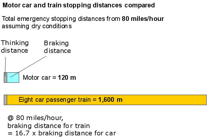
Rail's problem is that while road vehicles only have to stay a couple of car lengths apart, trains have to be about a mile apart. This is because the stopping distances are so much longer - rails being slipier than tarmac and carriages much heavier. For a long time John Redwood has been saying rail should learn from bus technology and build much lighter vehicles. This is also obviously far more fuel efficient. He is right on that . I also think we should be building automated rail which, by allowing single carriage units running 24/7 would increase capacity.
But here is another idea. A new magnetic braking system:
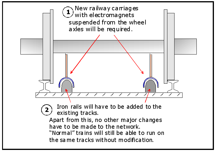
Here is a summary of the changes needed:
To prevent the outer faces of the Dewar flasks icing up in winter they can be fitted with heating elements to keep their temperature just above 0oC.
The previous arguments that it made economic sense were ludicrous and have had to be dropped. At about £80 bn, if it had to make a 10% return on capital as is normally expected that would cost £300 per ticket plus the natural running cost - this clearly does not make economic sense.
So back to overcrowding.
Rail's problem is that while road vehicles only have to stay a couple of car lengths apart, trains have to be about a mile apart. This is because the stopping distances are so much longer - rails being slipier than tarmac and carriages much heavier. For a long time John Redwood has been saying rail should learn from bus technology and build much lighter vehicles. This is also obviously far more fuel efficient. He is right on that . I also think we should be building automated rail which, by allowing single carriage units running 24/7 would increase capacity.
But here is another idea. A new magnetic braking system:
Here is a summary of the changes needed:

The problem with existing railways-poor grip when braking
Railway train wheels have a poor grip on steel tracks, compared with rubber tyres on roads. This severely reduces the ability of trains to climb inclines, accelerate or brake rapidly.
The minimum safe time interval between high speed trains using the same length of track is about 3 minutes, but for a car travelling at the same speed it is only a few seconds.
The minimum safe time interval between high speed trains using the same length of track is about 3 minutes, but for a car travelling at the same speed it is only a few seconds.

A solutionWe propose an electromagnetic traction and braking system for trains. Ina addition to significantly reducing braking distances, it will eliminate nuisance traction problems caused by "leaves on the lines".
Maglev trains are hover trains. They were invented in Britain in the 1960’s by Professor Eric Laithwaite and are now running in China.
They offer several advantages: Wear on the track is minimal and acceleration, braking and fuel economy all improve,
but these benefits are outweighed by the high track building costs.
They offer several advantages: Wear on the track is minimal and acceleration, braking and fuel economy all improve,
but these benefits are outweighed by the high track building costs.
Magtrac is simpler and cheaper than Maglev.
Our breakthrough:We reduce costs by mounting the electromagnets on the trains instead of the tracks.
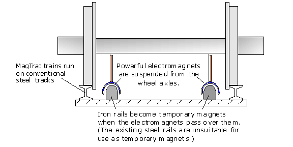
The electromagnets are suspended under the train and interact with soft iron rails mounted on the existing railway track sleepers.
The braking and acceleration benefits of Maglev are maintained, but Magtrc’s levitation effect is not sufficient to support the weight of the train.
The braking and acceleration benefits of Maglev are maintained, but Magtrc’s levitation effect is not sufficient to support the weight of the train.

Figure 2, Magtrac.
Q. Why are iron rails required?
A. Iron rails are better at amplifying the strength of the electromagnets but they rapidly lose their magnetism when the train passes. This eliminates the problem of steel cans and other ferromagnetic junk sticking to the rails.
A. Iron rails are better at amplifying the strength of the electromagnets but they rapidly lose their magnetism when the train passes. This eliminates the problem of steel cans and other ferromagnetic junk sticking to the rails.
1 HOW IT WORKS
We will build the Magtrac principle up in stages
1.1 The key concept
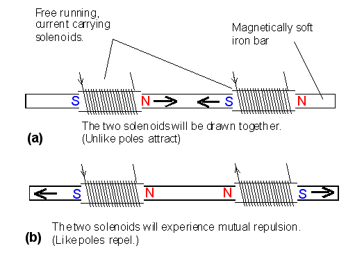
First we consider what happens when an electric current is passed through two solenoids resting on a soft iron bar.
[A solenoid is a cylindrical coil of wire that acts as a magnet when an electric current passes through it. The magnetic effect is weak if the interior of the solenoid is filled with air, but strong if the air is replaced by iron.]
The solenoids become electromagnets and either mutually attract or repel, depending on their polarities.

Figure 3. In addition to attraction or repulsion between the two solenoids, each solenoid experiences a repulsive force between itself and the enclosed soft iron bar. This provides a small levitation effect.
The law of conservation of energy has to be respected so we do not get "free" energy out of either of these arrangements. For example in Fig. 3 (a), after the solenoids have moved together, work has to be done against the magnetic attraction, to restore the magnets to their original positions.
We can't cheat nature by switching the magnets off and then moving them apart because when we switch the magnets back on again work has to be done against the back EMFs as the magnetic fields are rebuilt.
We can't cheat nature by switching the magnets off and then moving them apart because when we switch the magnets back on again work has to be done against the back EMFs as the magnetic fields are rebuilt.
1.2 A load carrying platform
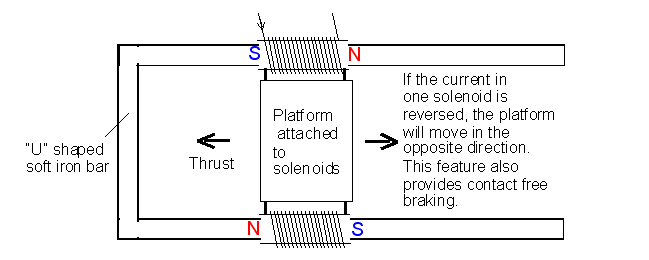
Plan view:

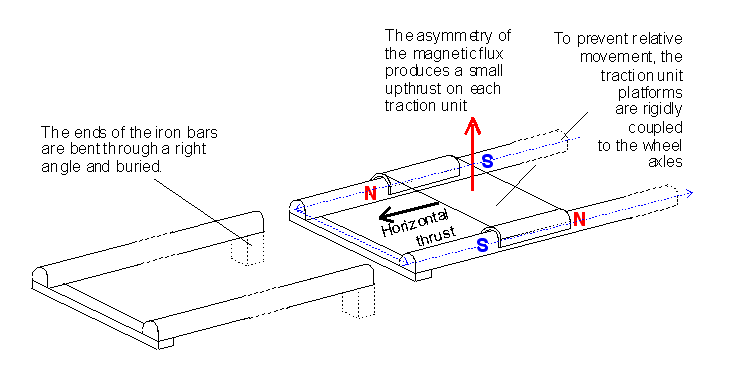
Figure 4. To move a lightweight platform along a short length of track, the soft iron bar needs to be bent into a U shape.
1.3 A practical traction unit
For the platform to move along a track of indefinite length:
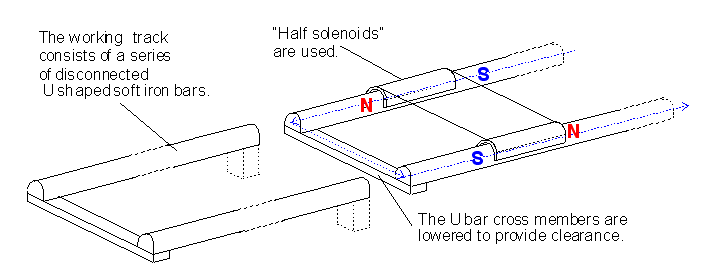
(i) A long chain of U shaped iron bars is required.
(ii) “Half solenoids” that can “jump” from one iron bar to the next are used.
(ii) “Half solenoids” that can “jump” from one iron bar to the next are used.

Figure 5. The platform and supporting half solenoids can move along an indefinite length of track

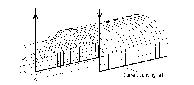
Figure 6. This is a “half solenoid”, with all of the windings connected in parallel. When an electric current flows through the windings, a magnetic field similar to a full solenoid is produced. But its asymmetry results in a net upward force when it rests on a soft iron bar.

Figure 7. An alternative, series winding. The neutralising effect of the upper half solenoid is minimal, because of its greater distance from the soft iron rail.

Figure 8. Further details of the electromagnetic coupling.
The up thrust is a useful bonus but it cannot be relied upon to support the weight of the train because it varies with the current passing through the half solenoids.
The up thrust on the train produces an equal and opposite down thrust on the iron rails. This improves the friction grip between the rails and underlying sleepers.
We will refer to the activated half solenoids as runners and the lengths of soft iron tracks as stators.
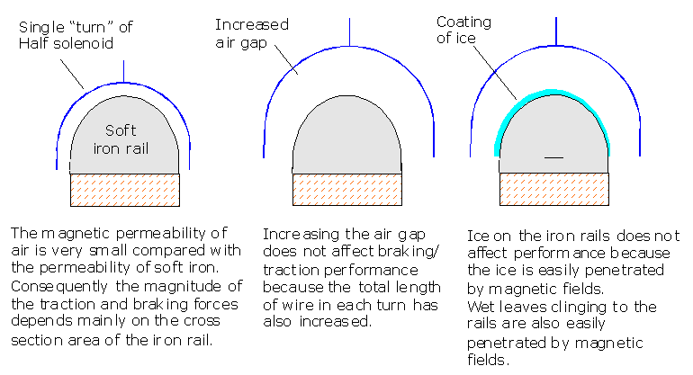
It is not necessary for the runners to be in close contact with the stators and large clearances between them are possible to avoid fouling by small items of debris. (Large clearance gaps require large diameter half solenoids. So the total length of conducting wires generating the magnetic flux increases, compensating for the larger air gap.)
Large clearances will allow wipers to be added, to periodically clean the under surfaces of the runners.
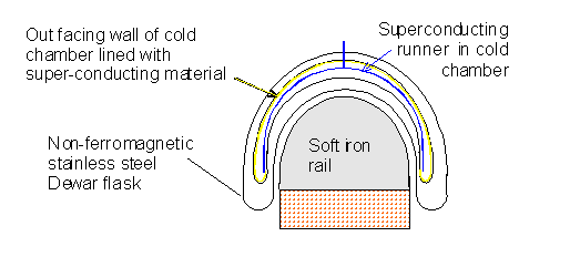
The conducting wires can be made from superconducting material and the half solenoids immersed in very cold chambers protected by Dewar insulation.
Skilled engineers will recognise that some technical details relating to back EMFs, current changes and the fate of kinetic energy lost during emergency Magtrac braking have been omitted. Nor has the configuration for regenerative Magtrac braking been revealed.
This is for intellectual property protection reasons.
This is for intellectual property protection reasons.
1.4 Explanation: Why the size of the air gap, ice and leaves on the rails do not affect performance

Figure 9. Icing of the iron rails will be a rare event because Magtrac has a built in de-icing mechanism.
When an iron rail goes through a magnetisation-demagnetisation cycle, a small amount of heat is generated. (Hysteresis loss.) This will help to melt any ice or snow in winter.
When an iron rail goes through a magnetisation-demagnetisation cycle, a small amount of heat is generated. (Hysteresis loss.) This will help to melt any ice or snow in winter.
The only downside of a large air gap is that the half solenoids are slightly bulkier, heavier and more expensive to build.
Q. How effective will Magtrac braking be?
A. Braking and traction increase with the total number of turns in all of the half solenoids, the currents passing through the wires and the cross section area of the iron rails. In principle, Magtrac braking could be as efficient as the braking on a Formula One racing car. In reality, a far more modest braking system should meet commercial, safety and customer needs.
2 Reducing stray magnetic fields
Stray magnetic fields can attract ferromagnetic debris such as nuts, bolts and nails. A number of steps can be taken to design this problem out of the system.
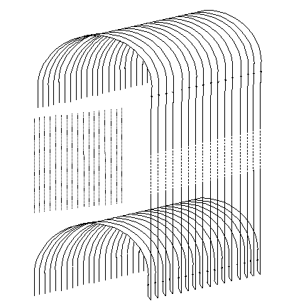
2.1 Superconducting shieldsFor superconducting systems the runners are lodged in cold chambers. Magnetic flux cannot penetrate a sheet of superconducting material, so by lining the out facing walls of the cold chambers with superconducting material, magnetic flux shields can be created.
2.1 Superconducting shieldsFor superconducting systems the runners are lodged in cold chambers. Magnetic flux cannot penetrate a sheet of superconducting material, so by lining the out facing walls of the cold chambers with superconducting material, magnetic flux shields can be created.

Figure 10. Superconducting shielding.
To prevent the outer faces of the Dewar flasks icing up in winter they can be fitted with heating elements to keep their temperature just above 0oC.
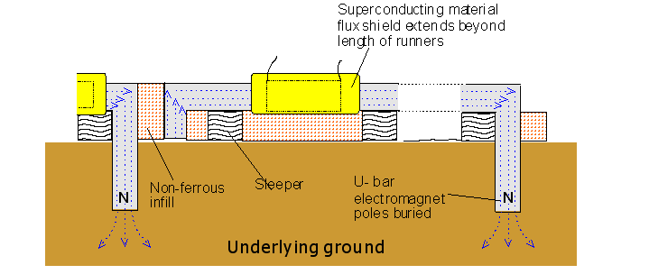
2.2 Bury the poles of the soft iron magnets

Figure 11. A vertical cross section at track level.
2.3Additional measures to prevent damage by small items of debris include mounting miniature "cattle fenders" and scavenging electromagnets ahead of each item of rolling stock.
3 Keeping the runners and flux shields cold
Runners and flux shields can be chilled using liquefied gases or dedicated refrigerators. A combined system may be best.
New designs of cryocoolers (low temperature refrigerators) created for use with rolling stock are published on our superconductors and cryocoolers web page.
New designs of cryocoolers (low temperature refrigerators) created for use with rolling stock are published on our superconductors and cryocoolers web page.
4 Powering Magtrac trains
Don't get can carried away with the idea of a free ride. If the electromagnets are superconducting there are no heat losses but energy still has to be expended driving the electric currents against the back EMFs produced as the train moves.
Electrification is one option, but burning hydrogen is preferred because the fuel can be used twice. First in liquid form, as a superconducting temperature coolant; then as a fuel to generate electricity.
To burn the hydrogen fuel efficiently onboard we propose using our Latent Power Turbines.
5 The copper alternative to superconducting windings
The argument in favour of superconducting windings is that they eliminate electrical resistance (Joule) heating losses. Copper is not a superconductor at liquid hydrogen temperatures but its resistivity is les than 5% of its value at UK average temperatures. If copper is used for the windings there will still be some Joule heating losses at low temperatures but the thermal energy can be used for warming the hydrogen prior to its use as a fuel.
Copper is easy to handle when manufacturing the half solenoids and has the safety bonus that it can still be used for effective braking, even if the hydrogen cooling system fails.
Copper is easy to handle when manufacturing the half solenoids and has the safety bonus that it can still be used for effective braking, even if the hydrogen cooling system fails.
6 "Belt and braces" braking systems
6.1 Friction brakes would still be used as a backup and to prevent stationary trains rolling down hills.
6.2 Each carriage would have wheel axles coupled to motor/generators, to provide regenerative braking during normal journeys. This energy could be stored in lithium batteries.
6.3 Each carriage would also be fitted with its own Magtrac electromagnets. In the event of the principle Magtrac power supply failing, power from the batteries would be used as a backup.
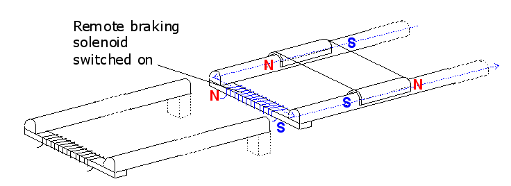
6.4 Remote braking On the approaches to potential accident spots such as railway crossings, active Magtrac rails can be installed. These would include externally powered solenoids that converted attraction into repulsion. This would allow remote braking by an external operator or an intelligent CCTV system.

Figure 12. Active Magtrac rails include current carrying solenoids that can be switched on remotely. These instantly convert traction power into braking power.
Braking solenoid off: Axle mounted N attracts second 1/2solenoid axle mounted S. Traction power is generated.
Braking solenoid on: Axle mounted N repelled by Magtrac rail mounted N. Braking power is generated.
Braking solenoid on: Axle mounted N repelled by Magtrac rail mounted N. Braking power is generated.
If the track based system detects that the trains half solenoid currents have been changed to initiate braking, the track solenoid current can be switched off.
The UK mainline Health and Safety report for 2012 records four pedestrian and five car deaths on level crossings.
Protection for maintenance staff Portable half solenoid versions of the the remote braking system could be installed on lengths of track where maintainable work is being carried out while the track is still in use.
7 PointsThere would be no Magtrac iron rail in close proximity to points. If necessary, the axle coupled motors would be used to shift stationary trains away from these sections.
8 Noise reduction bonus
The elimination of friction as the primary source of braking, combined with the reduced wheel on track loading, thanks to the Magtrac up-thrust, will significantly reduce train noise.
Magtrac eliminates the squealing of friction brakes and the vibrations caused by uneven wear on the steel tyres resulting from friction braking.
---------------------------------------------
Braking "like a Formula One car" is indeed unnecessary but if it were even equal to normal road transport, 10 times faster than currently, the capacity of the rail system would increase massively. Presumably not 10 fold because the new bottleneck would be the size of stations (which could be expanded) but easily enough to increase rail traffic several fold which would work for the foreseeable future.
This would be far cheaper and installed far faster than HS2 and would improve rail transport for the entire country.
I recently described shale gas as being an example of the second generation of technological breakthroughs stifled by politics (nuclear being the first) and this is the 2nd (or perhaps 3rd) generation of technological progress in rail transport (lighter vehicles and automation being the first two).
Once again we see we have non unsolvable, or even particularly difficult problems except getting rid of the government parasites whose continuing power depends on keeping us fearful and eager to be led by making the problems seem worse.
Labels: Big Engineering, British politics, Government parasitism, Science/technology
Comments:
<< Home
Neil - you and John Redwood appear to not know the basic physics of friction. Friction is relatively independant of weight. A heavier vehicle on the same track will produce a larger friction force. The key determinant is the coefficient of friction between the wheels and the track. Where lighter weight could be an asset is where additional down force can be applied by aerodynamic or other means. Whilst electromagnetic braking can and does work it is not fail safe as it requires a continuous power supply. If power is interrupted or fails - so does your electromagnetic braking system.
But inertia and mass are the same.
Fair point about power outages but the trains could then stop - which would cause enormous problems but would have to happen now if an outage stopped train signals.
Fair point about power outages but the trains could then stop - which would cause enormous problems but would have to happen now if an outage stopped train signals.
No inertia and mass are NOT the same. They have the same units and this "coincidence" is a fundamental problem of physics.Inertia is a property of mass, but inertia is altered by more than mass. The spatial distribution of mass affects it's inertia. A heavier train will have more friction to slow it down, but requires more because that increased mass requires more force to achieve an acceleration or deceleration. Braking systems in heavy road vehicles are fail safe because the pnuematic system is working to to hold of the powerful springs working the brake pads. Failure of the air supply means the brakes come on and stay on. This cannot happen with electromagnetic braking unless a back up power supply kicks in ( and Out ) automatically
a bathing ape
kobe sneakers
golden goose outlet
supreme clothing
golden goose sneakers
air jordan
supreme hoodie
yeezy shoes
golden goose starter
kyrie irving
kobe sneakers
golden goose outlet
supreme clothing
golden goose sneakers
air jordan
supreme hoodie
yeezy shoes
golden goose starter
kyrie irving
The Laffer Curve is an important economic concept that has a primary effect on government revenues. ipvanish coupons code It provides a valuable insight into how taxation affects the economy, and helps us make better decisions about how to maximize government revenues. It's a great tool to have in our toolbox of economic knowledge.
Post a Comment
<< Home

